

Edited English translation of the original Chinese case. The original images and on-screen Chinese text are retained. Model names and example settings describe that source version; check current model documents for a new project.
Integration requirement
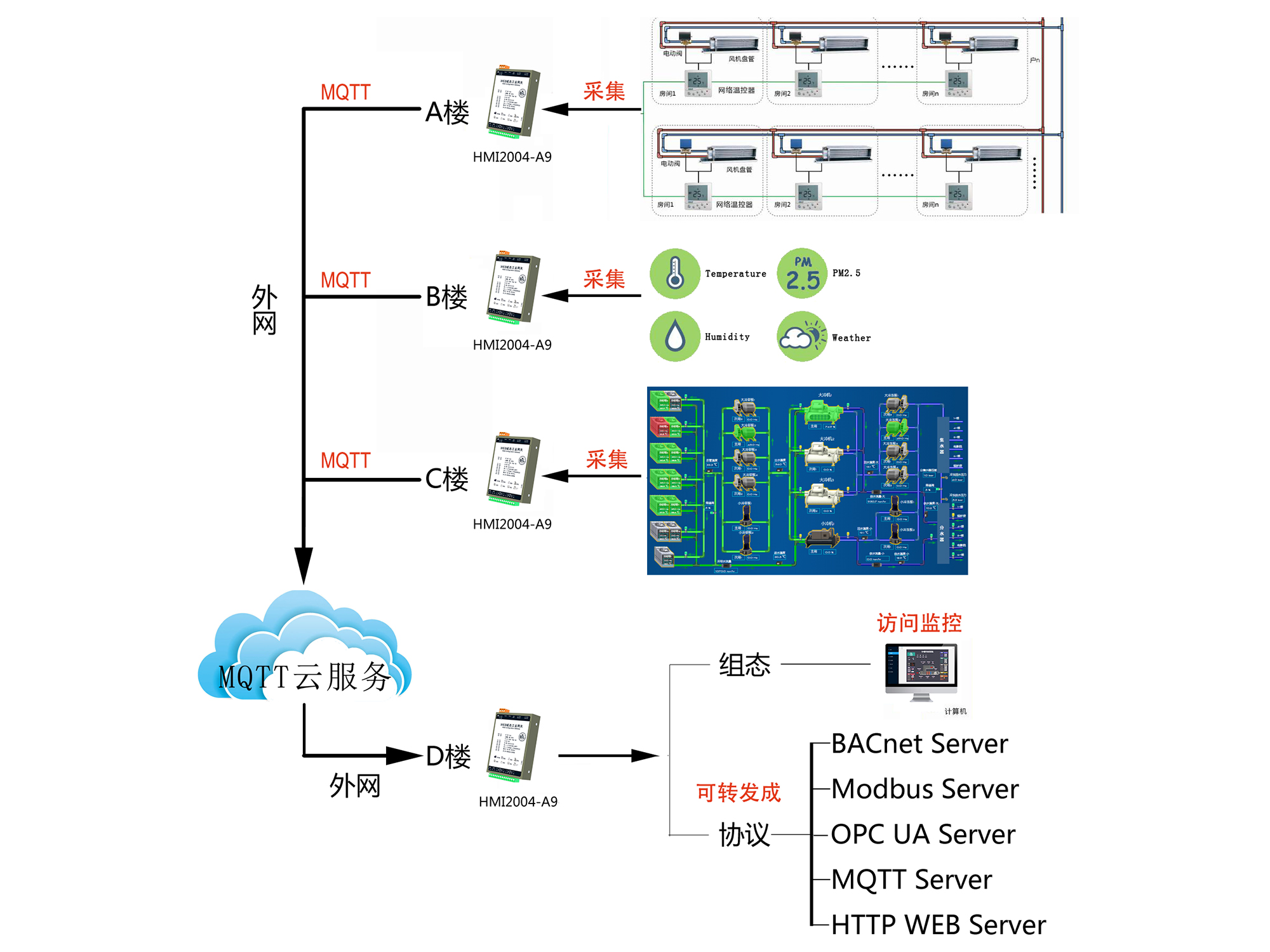
The source describes three separate building networks—A, B and C—whose data needs to be available at a remote headquarters, building D. The buildings do not share a direct local network. Each participating network must nevertheless provide the internet connectivity required by the proposed MQTT connection.
- Building A: laboratory temperature, humidity and other sensor points.
- Building B: HVAC points such as damper status, temperature, humidity and panel modes.
- Building C: water-system points such as pump start/stop status and runtime.
Gateway and connection concept
HMI2004-A9 gateways collect each site's points and exchange data through MQTT. Another HMI2004-A9 at D aggregates the remote data into the headquarters network. The source describes enabling the required forwarding-side service at D so that a local third-party system can access the collected points.
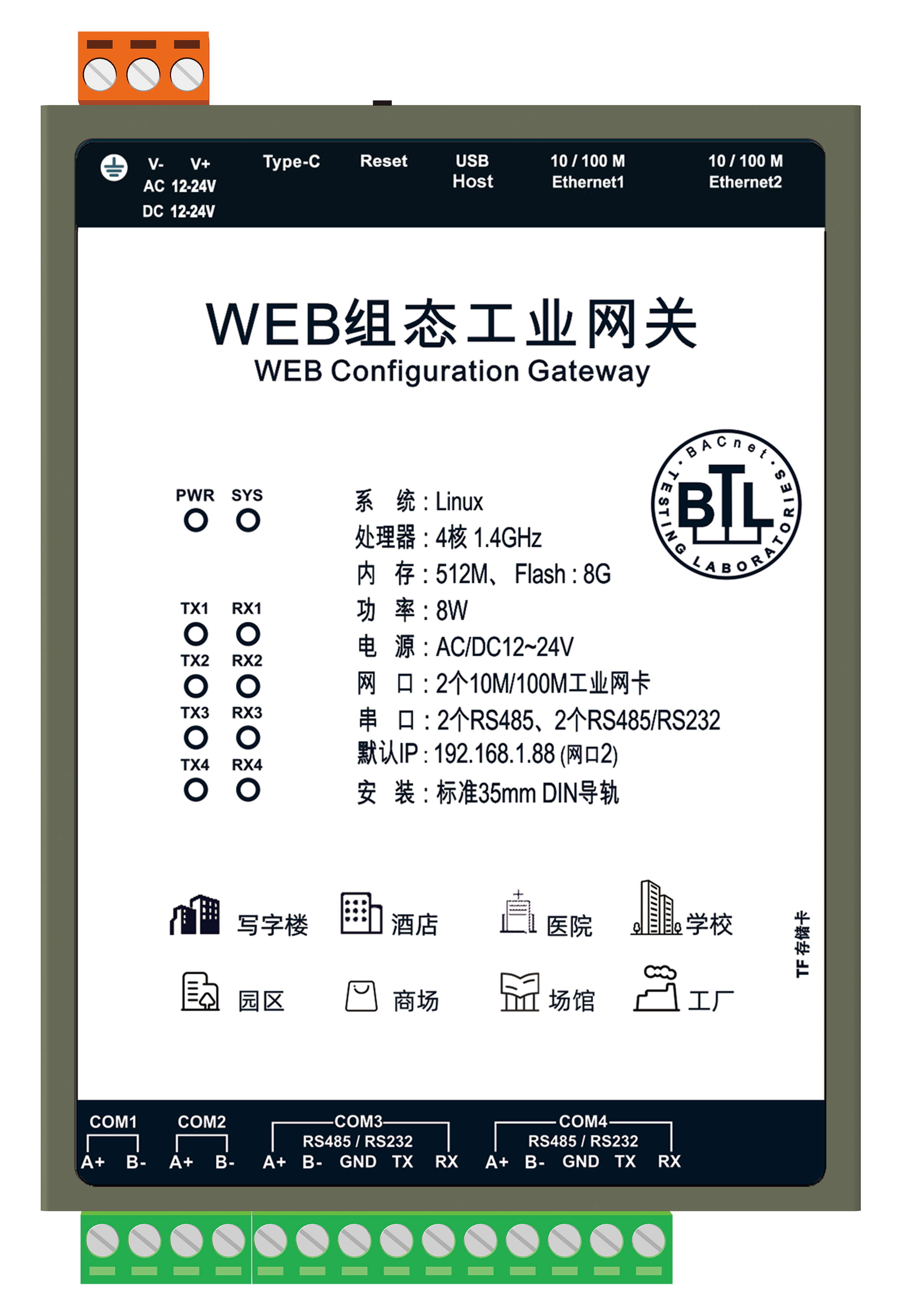
HMI2004-A9 shown in the source
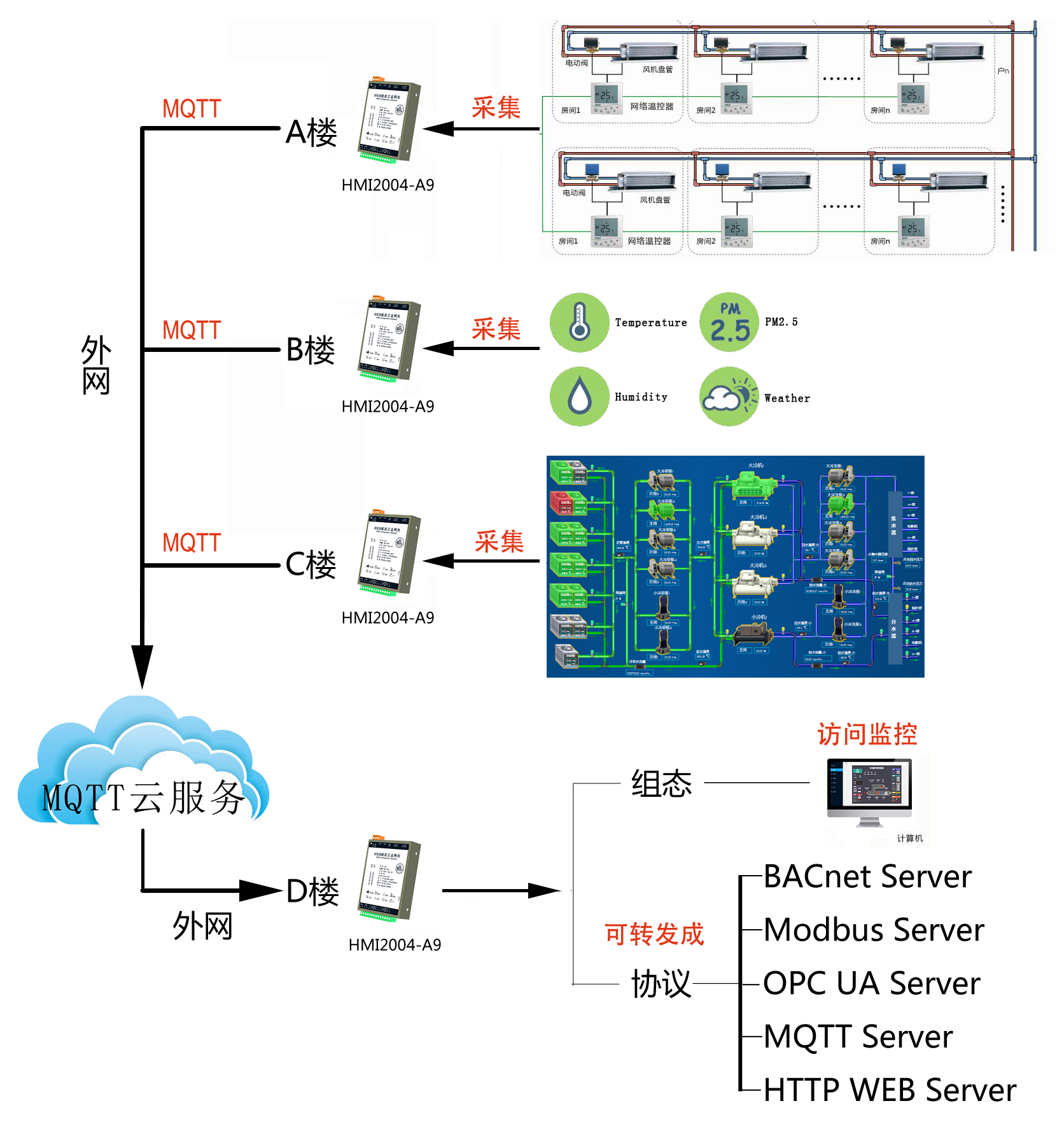
Original remote-data aggregation diagram
The services named in the source include BACnet, Modbus, OPC UA, MQTT and an HTTP web interface. Its general product introduction additionally mentions IEC 61850 and alarm channels. These lists describe the original material; they do not establish that every service is enabled, licensed or supported by every current model or firmware version.
Documented setup sequence
- Acquire and check the local point lists at A, B and C.
- Provide internet connectivity at each site and configure the gateway's MQTT exchange.
- Configure the receiving gateway at D to aggregate the remote data.
- Map the received points to D's HMI and to the forwarding protocol needed by the local supervisory system.
The source says the gateways use the same topic and “gateway ID.” It does not document the broker deployment, authentication, encryption, client identifiers or payload routing. Confirm the software-specific meaning of those settings before applying them to another project; the quoted terms do not provide a complete MQTT configuration.
Original data and HMI screens
Building A: laboratory
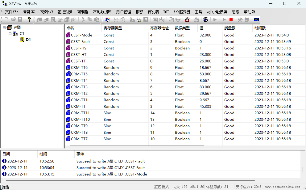
Building A laboratory point data
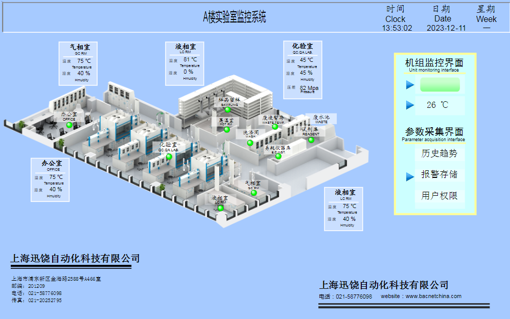
Building A laboratory HMI
Building B: HVAC
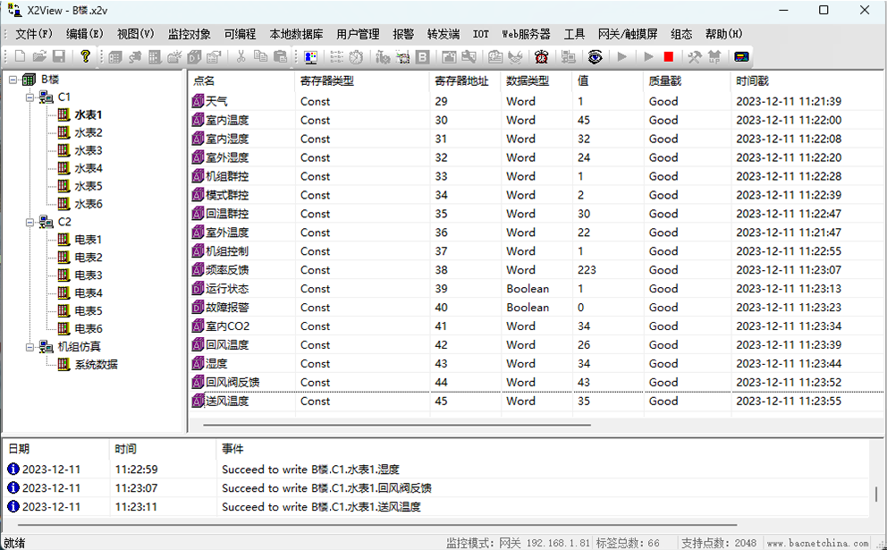
Building B HVAC point data
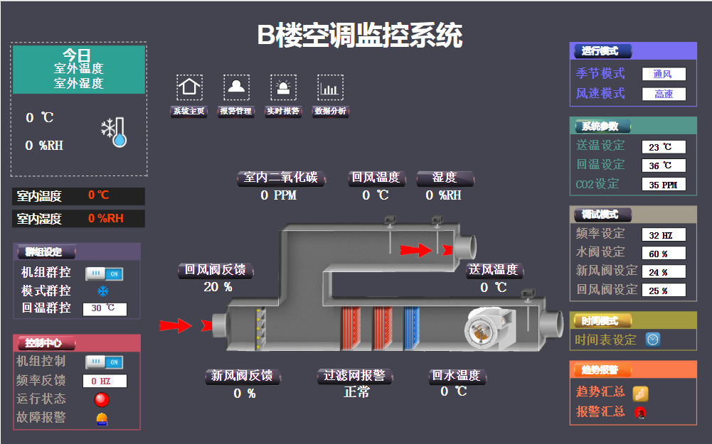
Building B HVAC HMI
Building C: water system
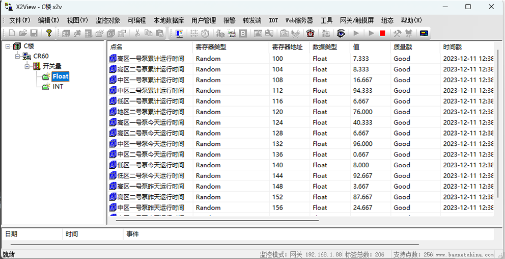
Building C water-system point data
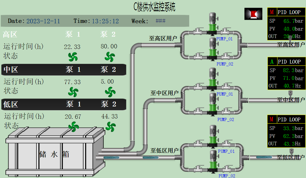
Building C water-system HMI
Building D: central view
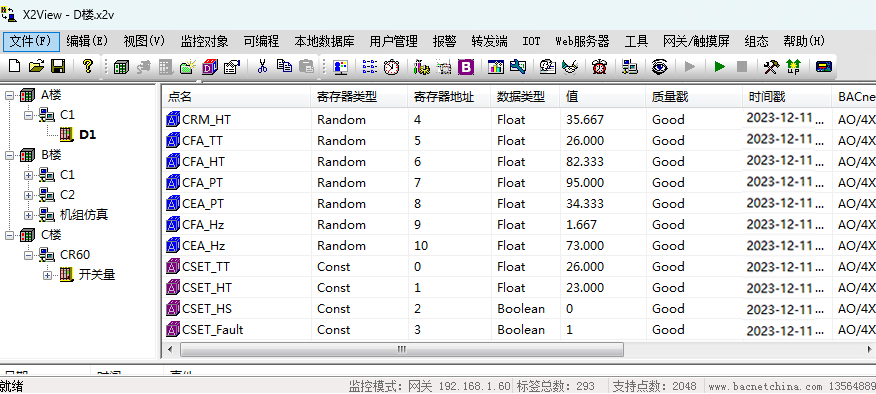
Building D aggregated point data
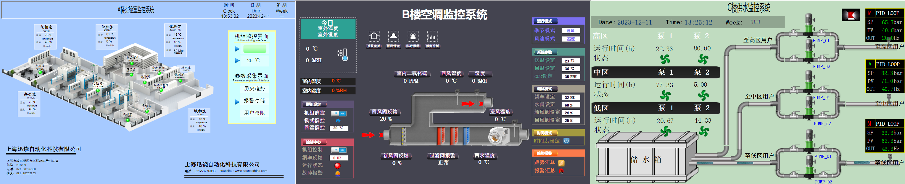
Building D central HMI
What the example establishes
The example illustrates protocol-aware remote aggregation, rather than simply forwarding an unchanged serial byte stream. The source discusses Ethernet, WiFi and 4G as possible internet-access methods; the actual interface or option must be checked on the selected hardware.
The original comparison with DTU devices contains broad stability claims but provides no loss-rate, throughput or end-to-end latency tests. Those claims are not a general verdict on DTUs or a measured guarantee for this gateway. Retain the topology and point-mapping concept, then assess network quality and the deployed version for the actual project.