

Edited English translation of the original Chinese case. The original images and on-screen Chinese text are retained. Model names and example settings describe that source version; check current model documents for a new project.
Site requirement
The source describes monitoring noise in an animal facility, with a focus on noise associated with construction tools. It requires recorded readings that can be exported, four alarm levels, a daily timer for noise exposure at each level, and an audible/visual alarm at the site.
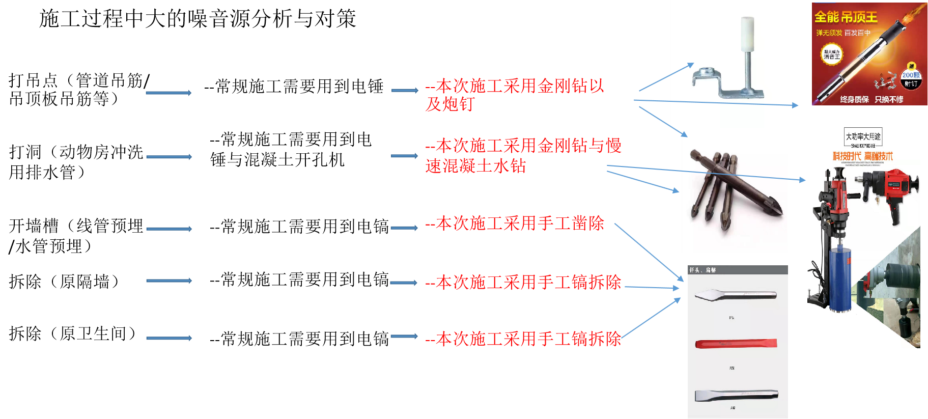
Original noise-source analysis
The stated configuration calls for one-second monitoring and one-second storage, live and historical alarm views, and clearing the day's alarm state and accumulated timers at midnight. These are the source project's requirements, not tested universal performance specifications.
Equipment and signal path
- One HMI2004-A9 gateway.
- Two Modbus RTU noise sensors.
- One Modbus RTU I/O expansion module, named IOM8400-ModbusRTU in the source.
- One audible/visual alarm unit with a dry-contact trigger.
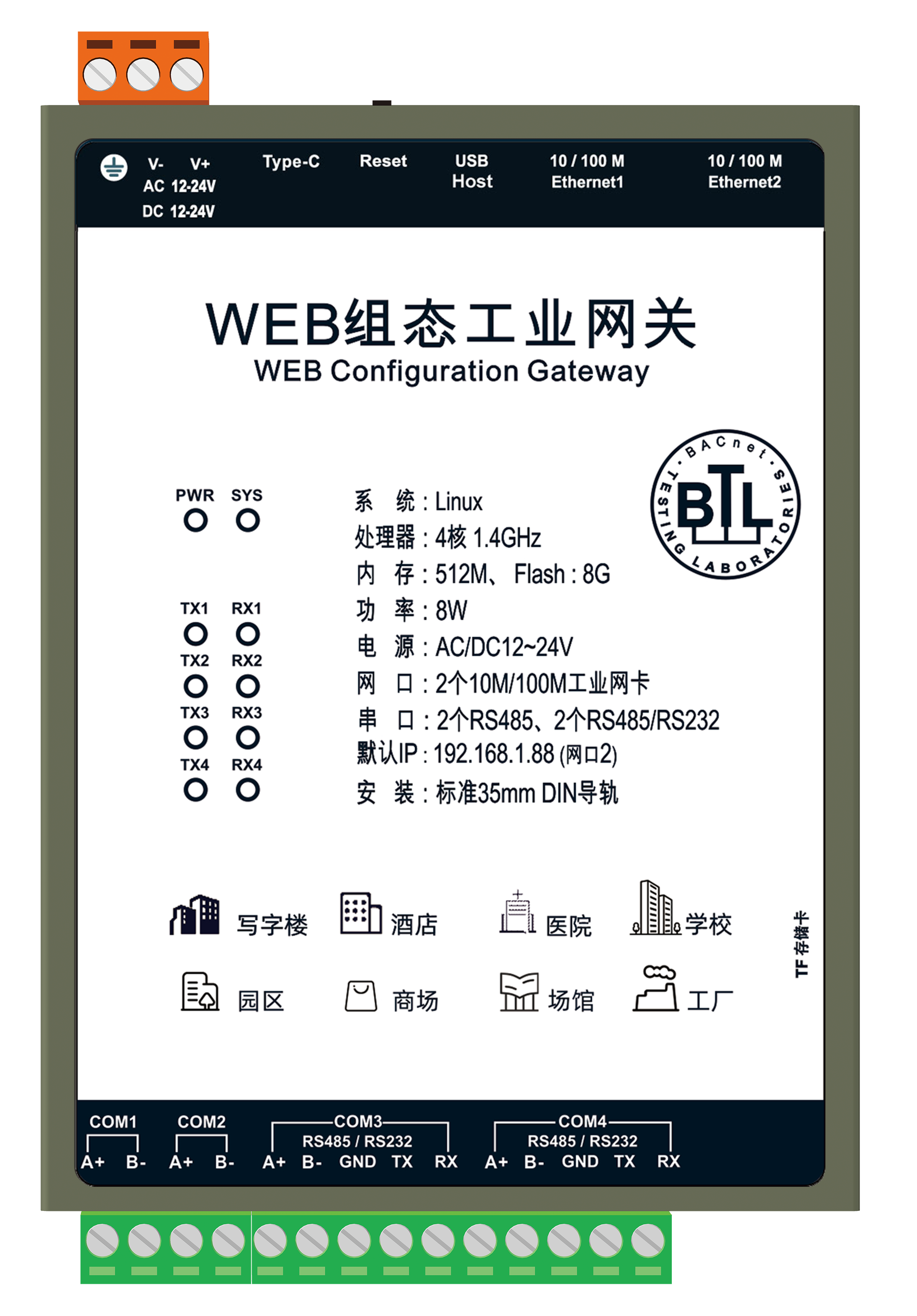
HMI2004-A9 in the source
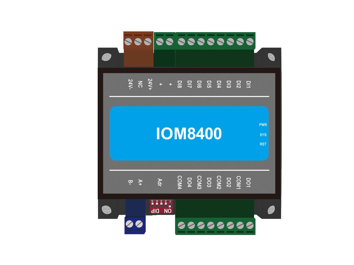
IOM8400 module in the source
The gateway reads the sensor values and evaluates the alarm logic written in its JavaScript function. The resulting command is sent to the I/O module's relay output, which triggers the alarm unit. The source describes RS485/Modbus RTU for the I/O connection and local time-series storage at the gateway.
Four alarm levels in this project
| Level | Noise threshold in the source | Source time setting |
|---|---|---|
| 1 | Above 72 dB | 60 minutes |
| 2 | Above 75 dB | 30 minutes |
| 3 | Above 78 dB | 15 minutes |
| 4 | Above 81 dB | 7.5 minutes |
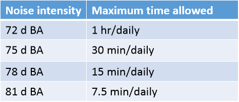
Original alarm threshold table
These thresholds and times are project settings, not a noise-compliance standard or a general health recommendation. The source uses both duration and daily accumulated-time wording but does not fully define every timer/reset condition. Use the original project script and requirements to determine how intervals are accumulated and reset.

Original monitoring and relay-alarm connection diagram
Recorded application screens
The source includes the following configuration, HMI, history and export views. The screenshots preserve the original interface text.
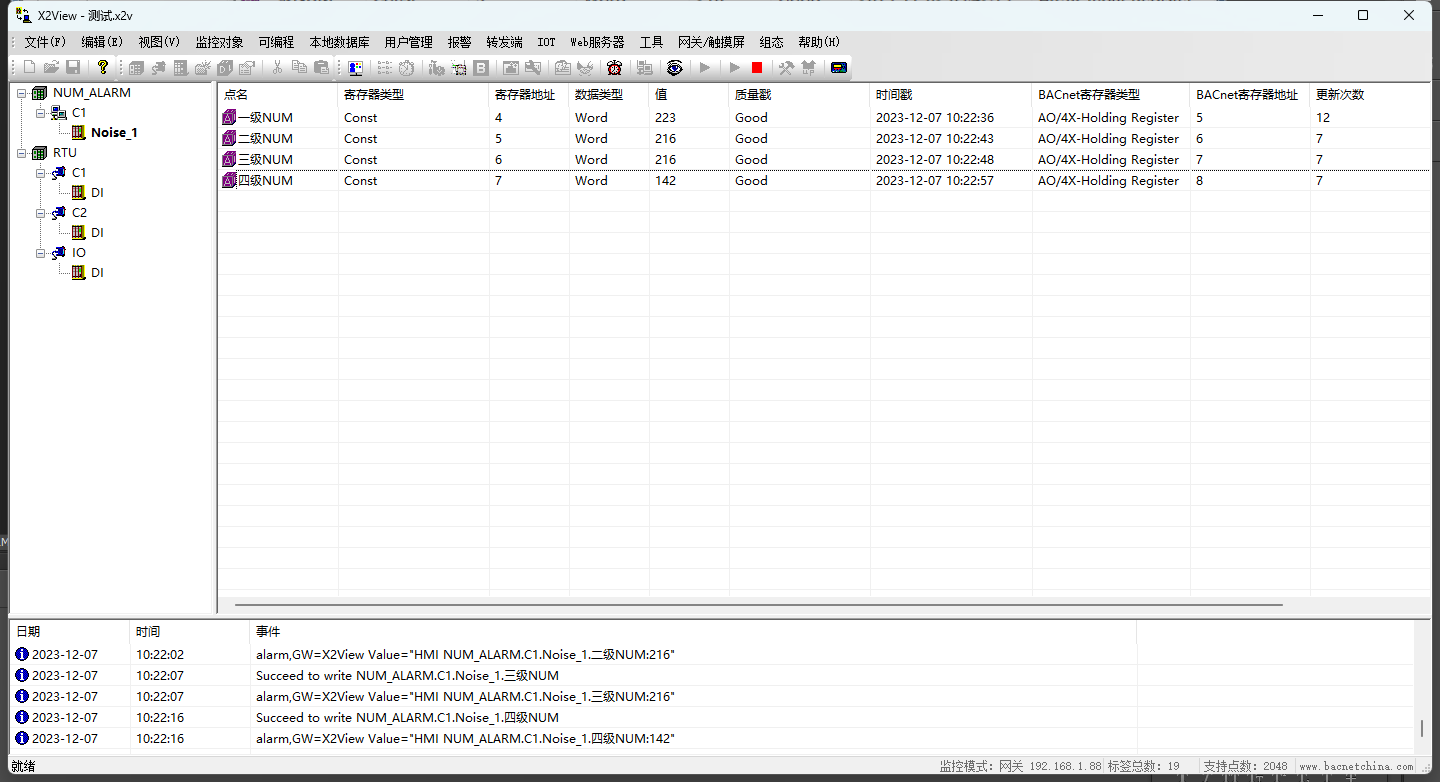
X2View point-monitoring screen
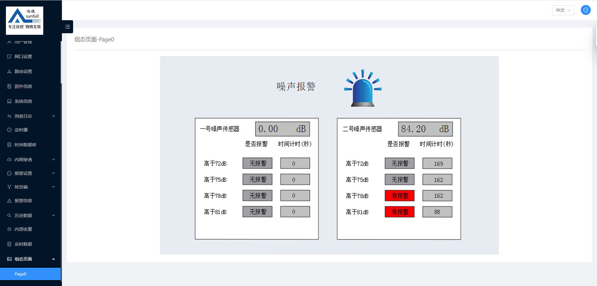
Noise-monitoring HMI
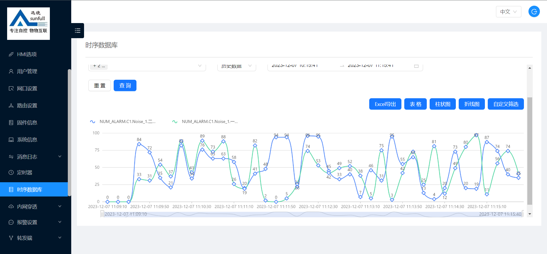
Historical data line chart
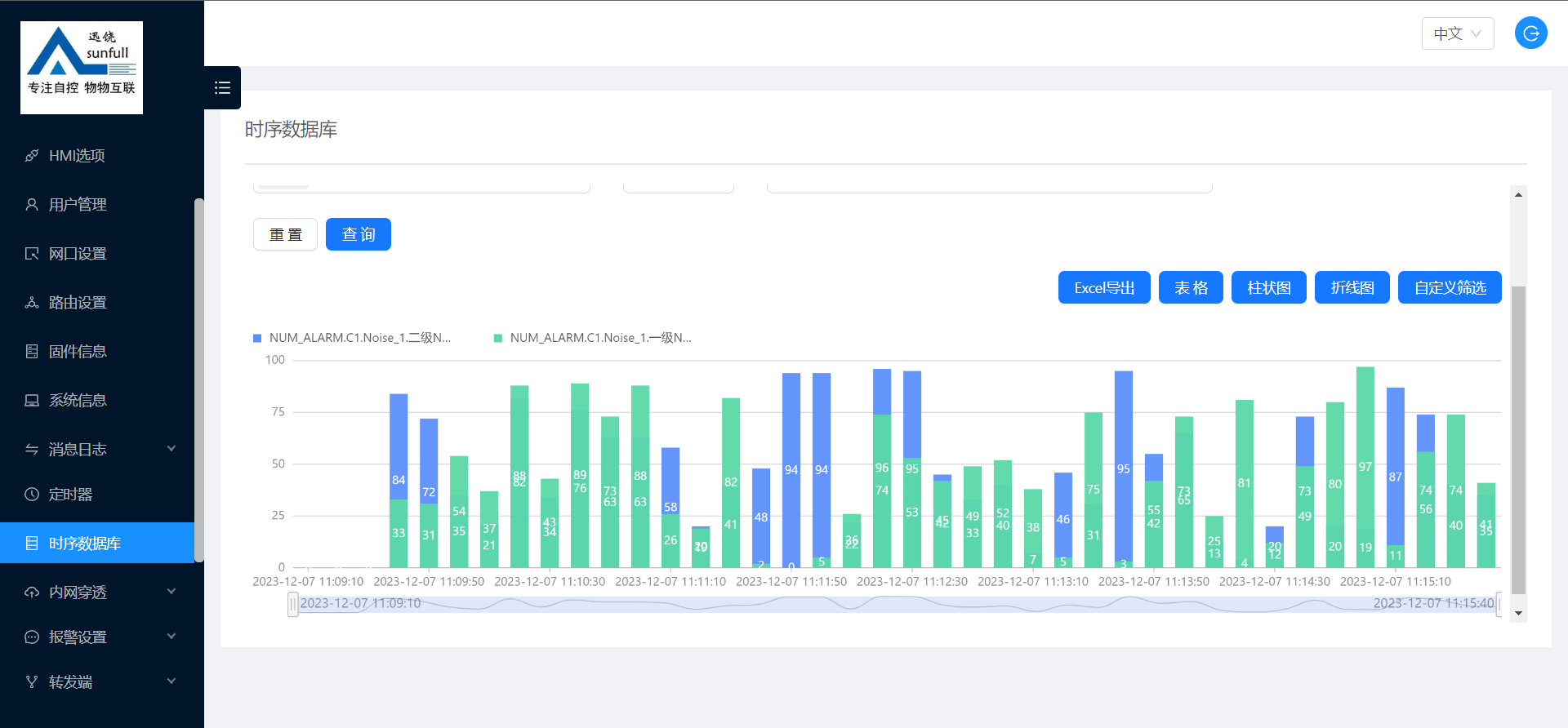
Historical data bar chart
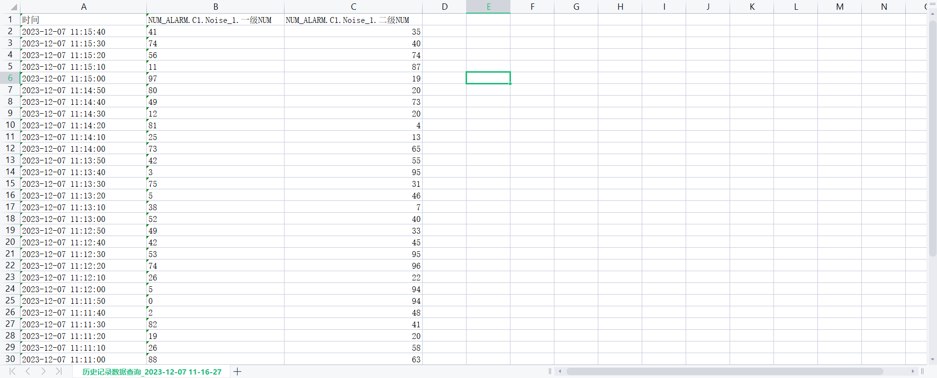
Historical data exported to a spreadsheet
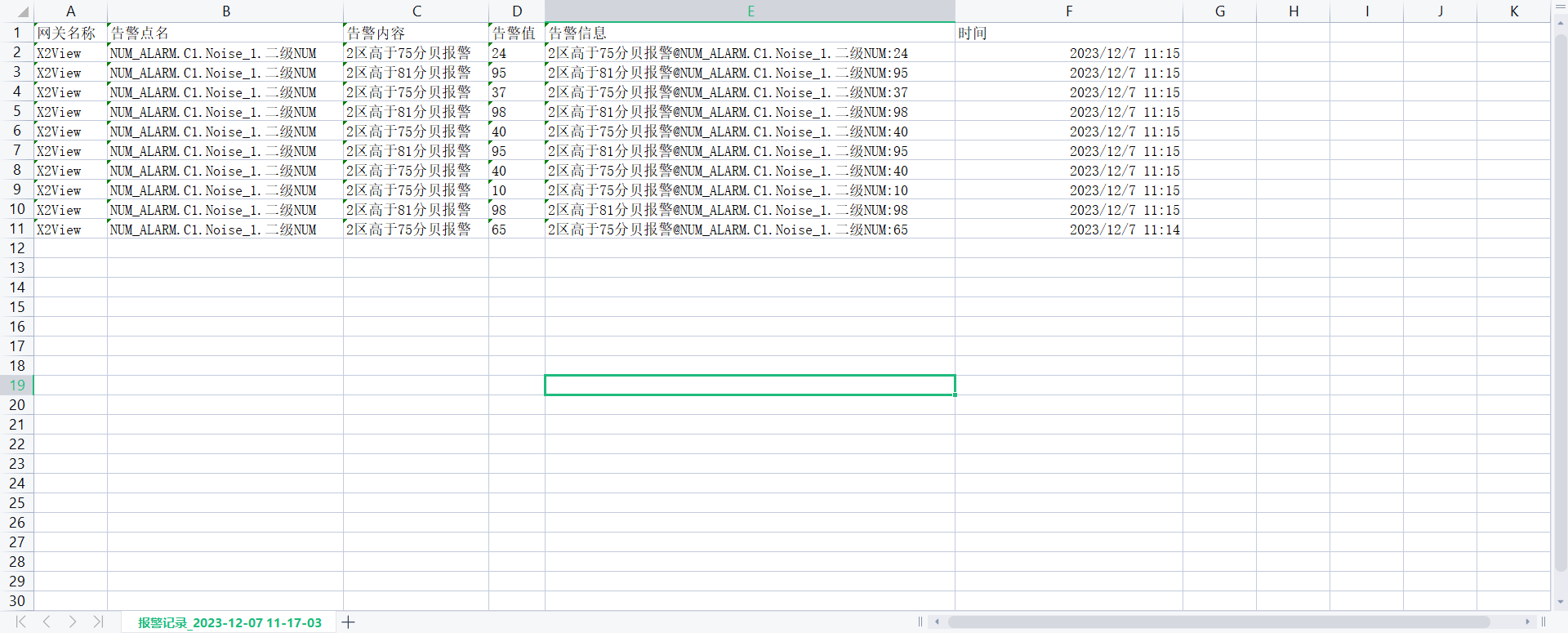
Historical alarms exported to a spreadsheet
Scope and implementation checks
The screenshots document the interface and export workflow presented by the source. They do not supply tests of measurement accuracy, end-to-end response time, false-alarm rate or sensor calibration. Confirm the actual sensor point map, scaling, sample/storage settings, timer behavior and output wiring for the deployed model and version.