

Edited English translation of the original Chinese case. The original images and on-screen Chinese text are retained. Model names and example settings describe that source version; check current model documents for a new project.
Project scope and equipment
The source describes an unnamed chiller-plant project, shown as “XX project,” rather than identifying a customer or publishing acceptance results. Its plant includes chillers, chilled-water and cooling-water pumps, cooling towers, valves and field sensors.
- HMI2004-A9 web HMI gateway: the network-level control engine, collecting points and providing the browser interface.
- BAC1002-ARM gateway: collects third-party equipment data and presents it in the protocol used by the HMI.
- DDC2001-8642 and IOM modules: the controller names recorded in this historical project, handling field inputs, calculations and outputs.
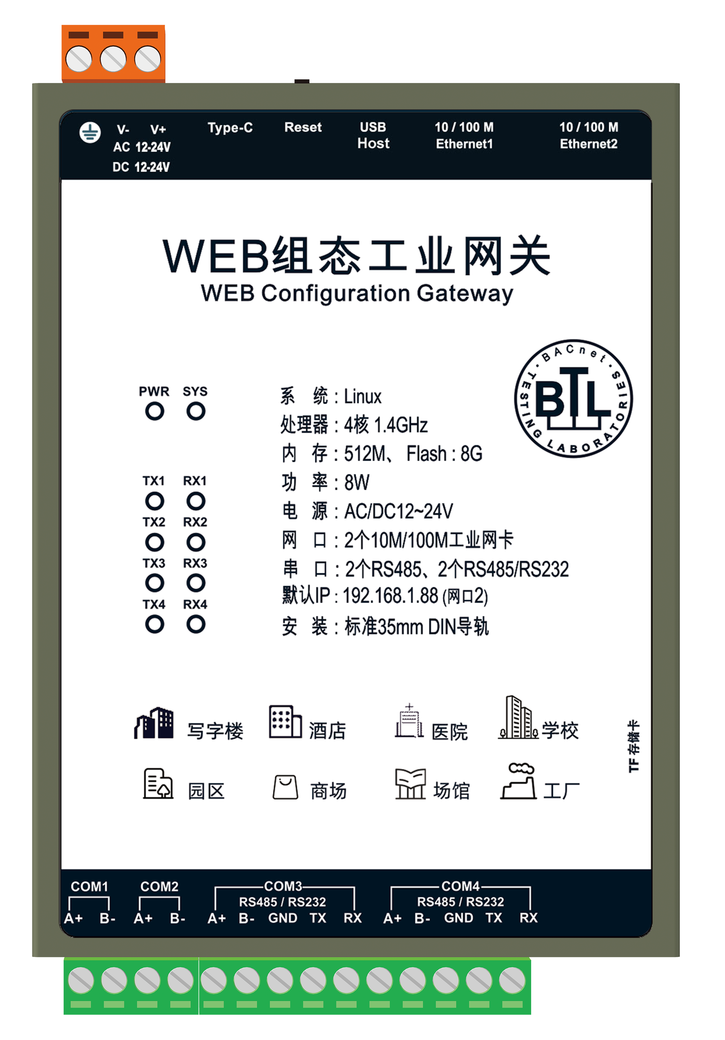
HMI2004-A9 in the original source
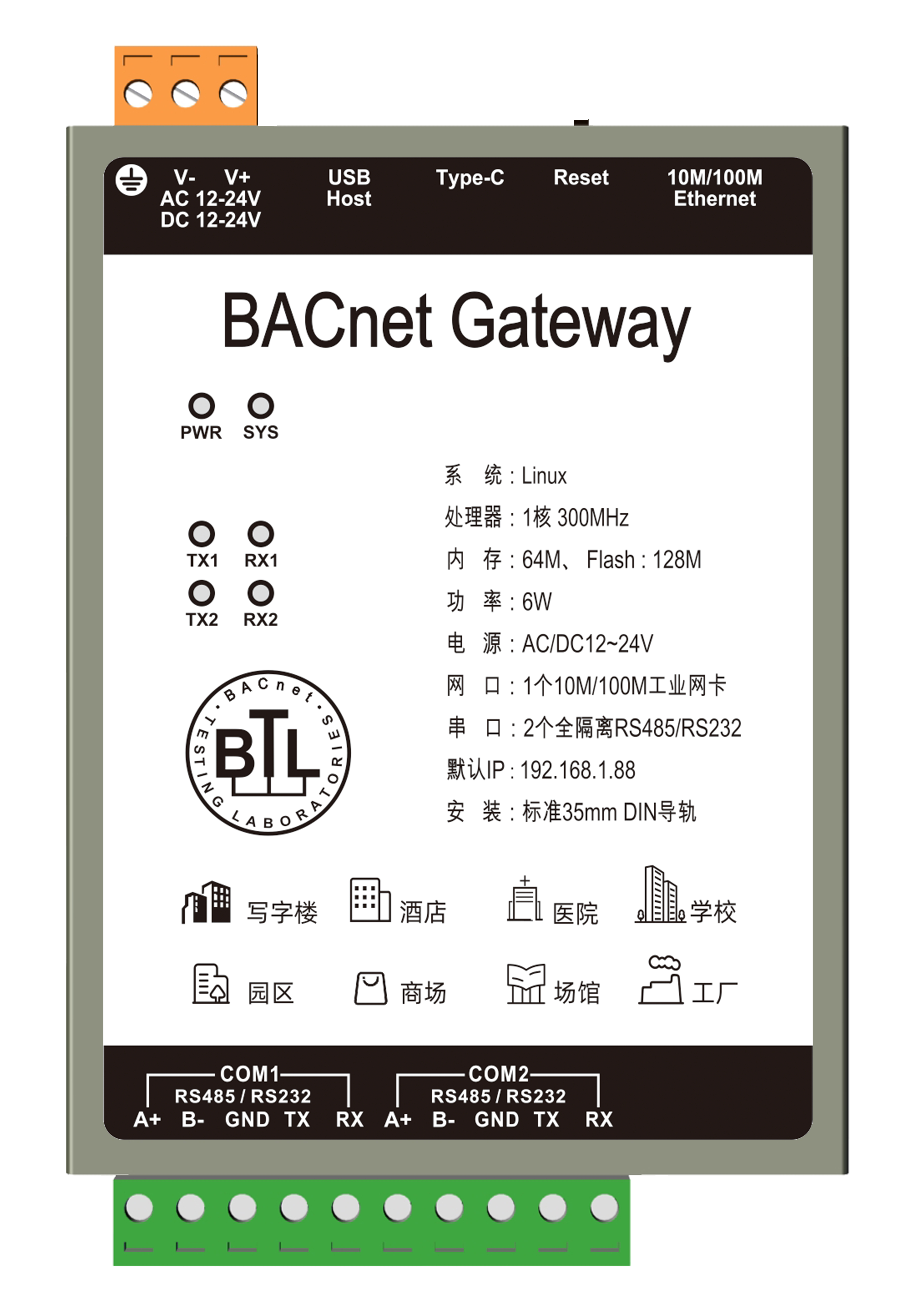
BAC1002-ARM in the original source
DDC controller in the original source
Data connection
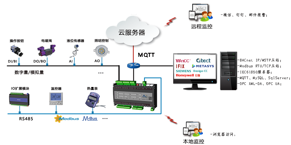
Temperature and pressure sensors, pump and tower status contacts, and valve commands and feedback are connected through the DDC and IOM modules. The source connects IOM to the DDC over BACnet MS/TP, then enables BACnet/IP forwarding from the DDC to the network.
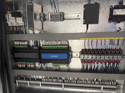
Original DDC and IOM assembly
Third-party equipment with Modbus RTU interfaces, such as chillers or water-treatment equipment, is connected through the BAC gateway. The documented network path uses BACnet/IP. The source also mentions Modbus TCP as an alternative; that is a separate configuration, not a second connection automatically present in this project.
The HMI gateway reads the DDC and gateway points over BACnet/IP and combines them with the project logic and graphics.
Configuration workflow
- Configure acquisition points in X2View from the equipment point lists.
- Write the project logic using JavaScript or the graphical programming interface.
- Use offline simulation to check and adjust the logic.
- Create the HMI graphics, bind their points, and upload the completed project to the HMI gateway.
- Open the gateway address in a browser to use the configured interface.
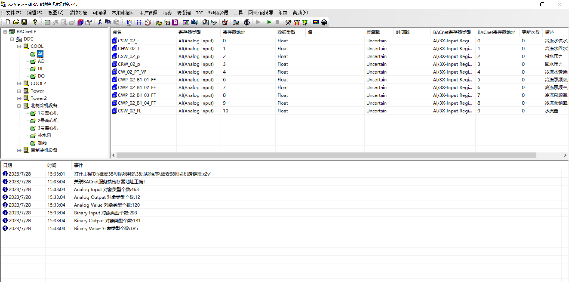
Point acquisition in X2View
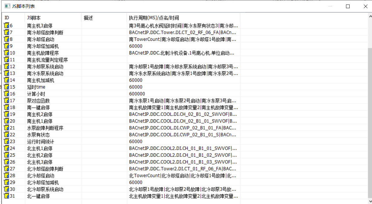
Original JavaScript programming screen
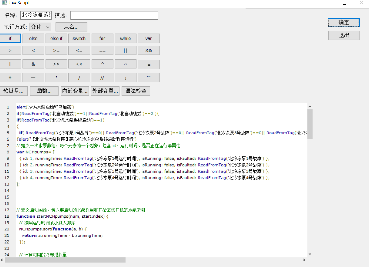
Original JavaScript example
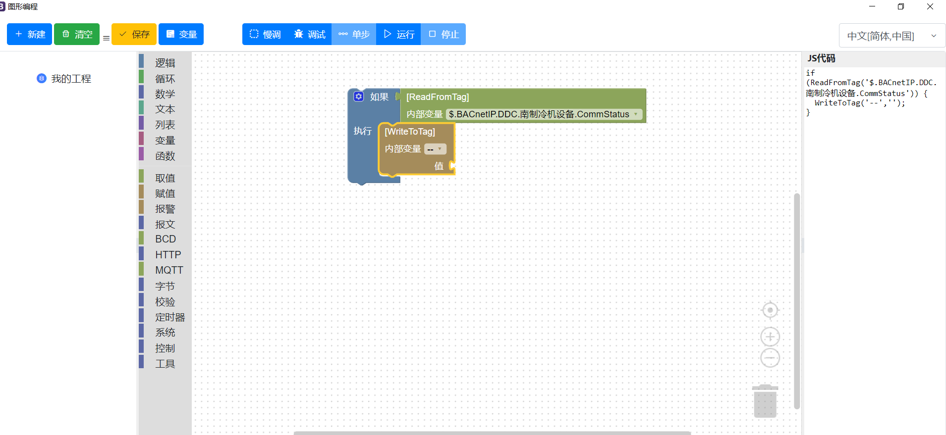
Original graphical programming screen
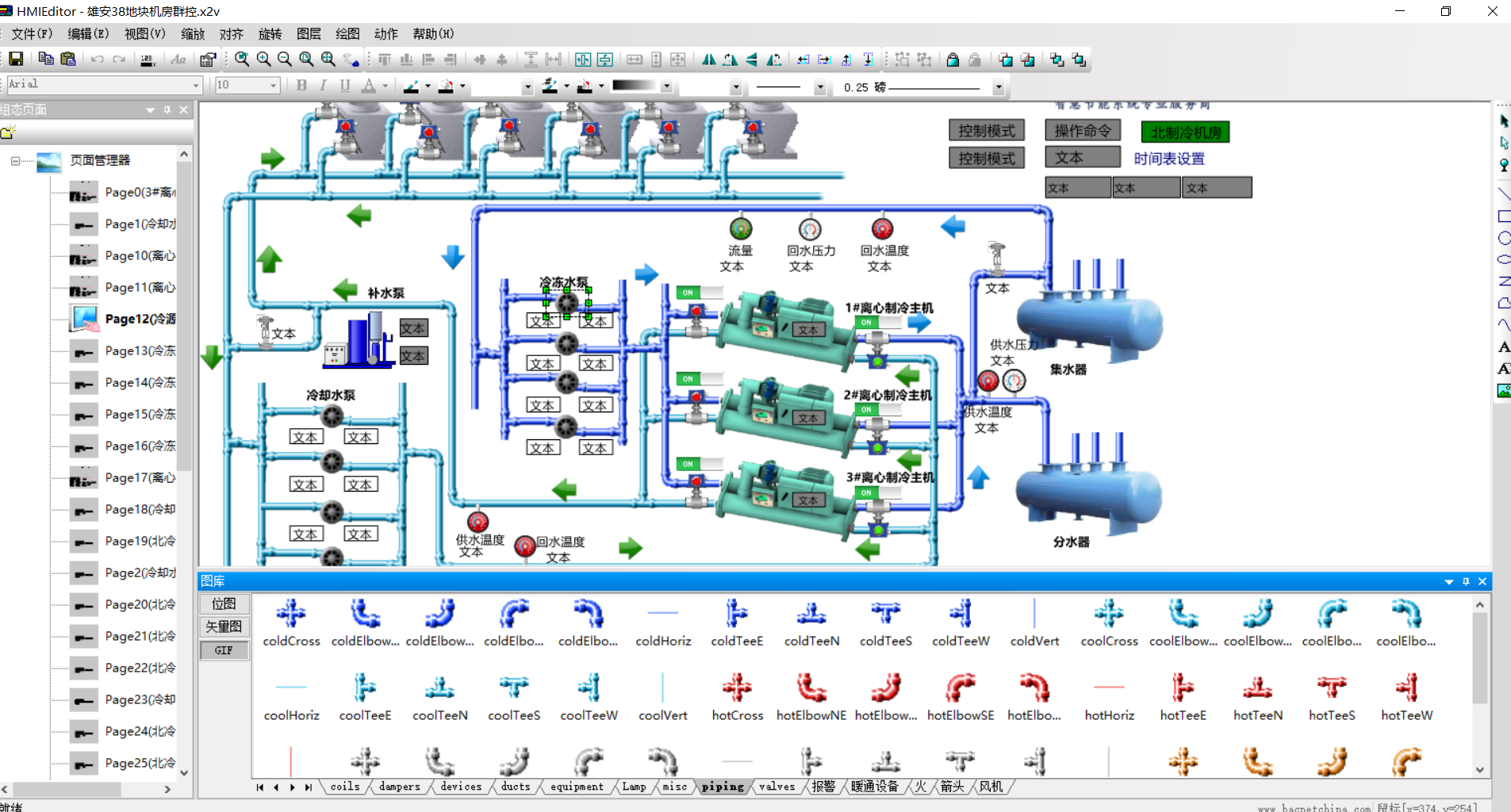
Original HMI editing screen
Operating the documented plant
Browser access and overview
The source opens a browser using the desktop icon  and enters the HMI engine IP address. The overview shows three centrifugal chillers; the upper-right selector changes between the north and south plant displays.
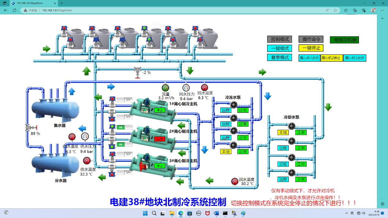
Original plant overview
The source illustrates the chiller 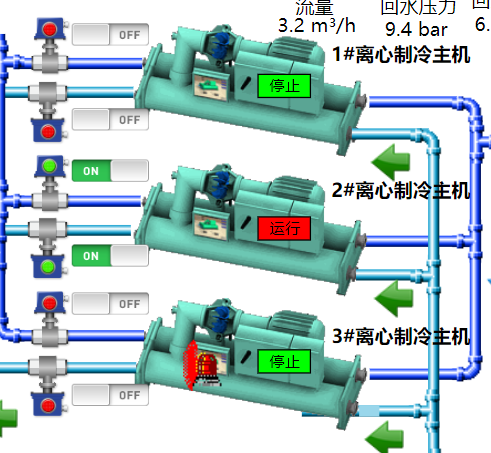 , chilled-water pump
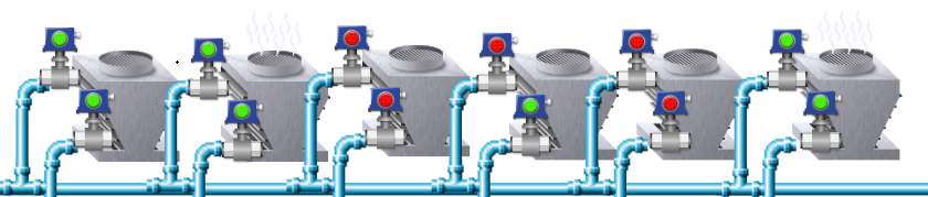
  , cooling tower
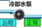
 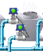 and cooling-water pump
  . Chilled-water and cooling-water bypass valves are shown as
  and
and 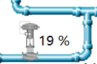 .
.
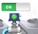
The on/off-valve graphic 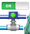 separates the command from feedback: the control bar shows the ON/OFF command, while the center indicator is green for fully open and red for fully closed.
Automatic, manual and one-touch modes
The mode selector 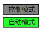 switches between the three project modes. In automatic mode, the source's chiller control
  coordinates the associated valves, pumps and tower.
The documented start sequence opens the chilled-water and cooling-water valves, starts the pumps and tower after the valves open, waits five minutes, then starts the chiller. Its shutdown sequence stops the chiller, stops cooling-water pumps and towers after five minutes, allows the chilled-water pump to circulate for 20 minutes, then closes the valves after a further documented delay of 30 minutes. These are the original project's settings, not general plant design values.
The source initially runs three tower fans and the corresponding valves. After a delay, its staging logic adds fans above 32°C cooling-water return temperature and removes fans below 27°C. The south plant has a different sequence: the cooling-water pump starts before the associated valve, followed by a delay and valve opening. That exception belongs to the original site's logic and must not be transferred to other equipment without reviewing its operating requirements.
In manual mode, pumps, chillers and valves are operated individually, either from the interface or at the equipment. The one-touch controls  apply only in one-touch mode. The source starts an available non-faulted chiller with the shortest recorded operating time, then uses chiller current percentage to determine staging. It describes two duty chillers and one standby chiller, with fault status and runtime influencing selection. One-touch shutdown stops chillers first and then stops the related pumps, towers and valves with delays.
The seasonal selector  changes the project between cooling and heating. In the original program, the cooling sequence runs in summer mode; seasonal valves select the associated heating or cooling path.
Pumps, towers and individual equipment pages
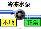
The plant has four chilled-water pumps, shown by 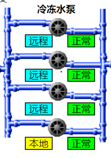 . The source distinguishes remote mode
  from local mode
  and shows a no-fault indication
  . The HMI controls the pumps only when they are in remote mode.
It also describes four cooling-water pumps 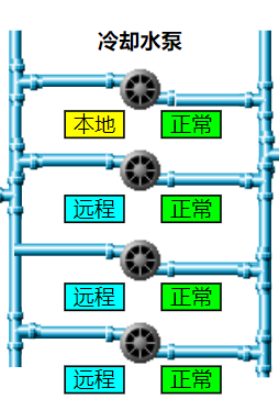 , with their own remote
  , local
  and fault-status
  displays.
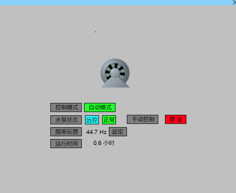
Original pump detail page
The pump detail page includes runtime and variable-frequency controls. The frequency button  accepts the project setpoint; the source imposes a 30 Hz lower limit while the pump is running. Its local override controls
  and
and  allow individual pump operation without changing the outer system mode. This is a description of that project interface, not a commissioning instruction for an unspecified pump.
Original pump frequency or control detail
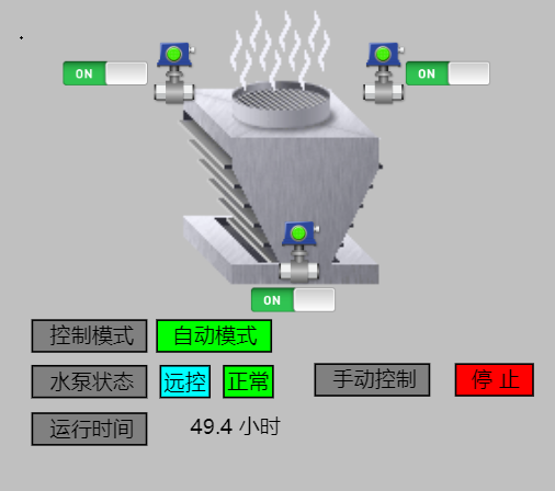
Original cooling-tower detail page
The tower page uses a similar override workflow, illustrated by  ,
,  and
and  . The source also calls for opening the associated valve on the overview
  .
.
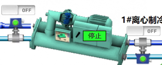
Original chiller symbol or control display
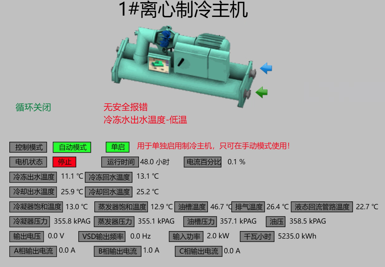
Original chiller detail page
The chiller detail page exposes the recorded parameters and a separate manual-start control  . The original text cautions that manual operation requires the associated valves, pumps and towers to be managed individually.
Weekly schedules and holidays
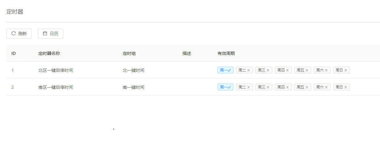
Original schedule page
The timer opens separate north-plant and south-plant one-touch schedules. Select a day, add a time entry 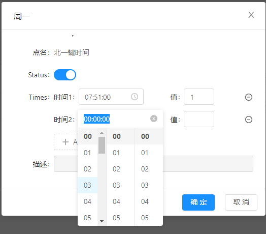 , and set its command: 1 for start and 0 for stop. Enable the entry
  and confirm it; the configured day is marked
  .
.
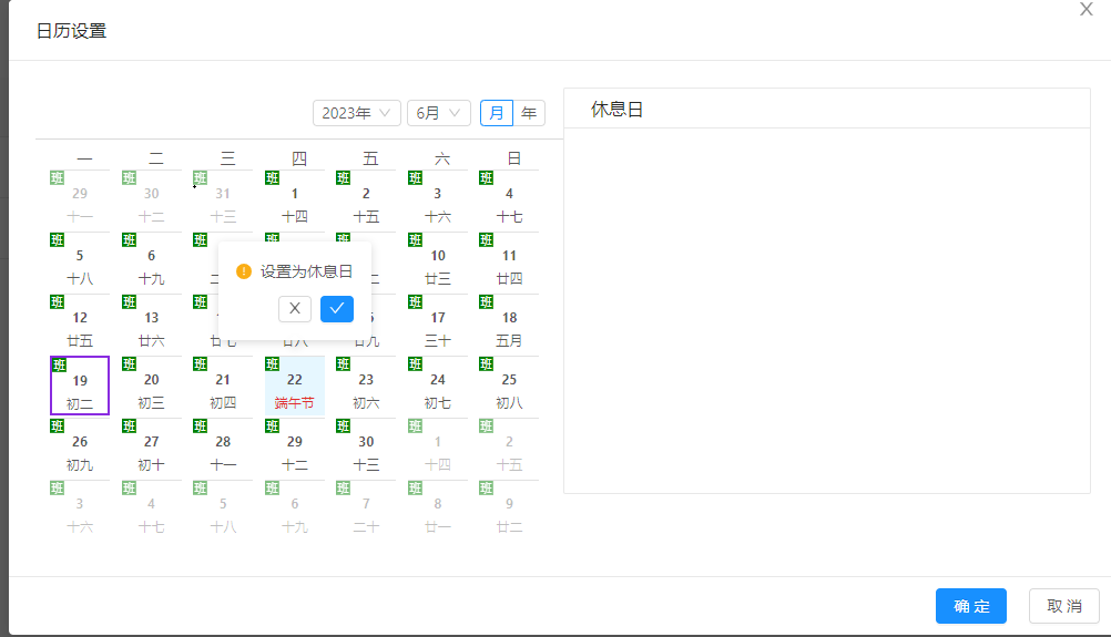
Original holiday calendar
The holiday calendar marks dates on which the ordinary weekly commands are not executed.
Version and project limits
Model names, display controls, interlocks, temperatures, frequency limits and delays above are taken from this historical example. Confirm the exact current model, hardware/firmware revision, point list and site program for a new project. The source does not provide measured energy savings, quantitative reliability results or an independent acceptance report.